Pusheng is an Asia leading chain link fencing supplier of permanent perimeter protection solutions with rich experience in the market. We supply hot dipped galvanized ( HDG) chain link fence and accessories to our customers worldwide. These include project solution design, manufacture according to specific standard and specifications, technical training and installation services.
Design:
Razor wire concertina on the top of Galvanized Chain link fencing and Steel Fencing, for finishing on the top end of fence and entrance gates.
This high security fencing solution include Chain Link Fence with Gate, Shade Netting for Privacy and Steel Fencing.
| No | Items | Description |
| 1 | Galvanized chain link fencing | Fence min. 2.2m high |
| 2 | Tubular section poles | 50mm Ø galvanised poles min. 2.70m high with 3mm wall thickness. |
| 3 | Gauge 10 SWG wires | 3 in no fence supported, 1 located at the top, 1 at the bottom and 1 located at the mid-part of the fence. |
| 4 | Heavy duty shade net | To cover fence and gates for privacy. |
| 5 | Wire/razor cut concertina | For finishing on the top end of the fence. |
| 6 | Site entrance gate | Made up of two-leaf galvanized chain-link fencing, size 4.00m x 2.20m high approx include 50mm tubular section poles. |
| 7 | Beams IPN160 | Galvanised steel beams 3m high. |
| 8 | Pedestrian gate | Made up of single leaf galvanised chain-link fencing, size 1m (W) x 2.16m (HT). |
| 9 | Steel fencing | Galvanized steel fencing min. 2.00m high and 3.00m wide, |
| 10 | Steel fencing | Brackets to connect the fences together and any other additional fittings to support fencing from falling. |
Specification for High Security Concertina Wire
| Description of Specification | Data of Specification | |
| 1 | Barbed tape Material | Stainless steel AISI 300 series compliant with ASTM A666. |
| Barbed tape thickness (mm) | 0.6 +/- 0.05 | |
| Barb Width (mm) | 21+/-2 | |
| Barb length -tip to tip (mm) | 65 +/- 2 | |
| Barb spacing (Cluster of 4) | 100+/-2 | |
| Concertina clip minimum pull load (kgs) | 181.44 | |
| Coil Diameter (mm) At Packing Status | (762 +/-50.8) | |
| Coil Loops | 101 | |
| Coil Spacing (mm) | 305+/-50.8 | |
| Roll Length (m) | 15 +/- 3.0 | |
| 2 | Minimum Tape Material wide prior to forming: 1.21 inch. (30.73 mm) | |
| Note: Core wire is not required; it is non-reinforced concertina. It shall be single coil. | ||
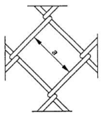
1. Mesh Size.
Distance measured at right angles internally between adjacent parallel wires. See figure below:
2. Chain Link Fencing
Fencing manufactures from the interlocking of steel wire helices which provide approximately square mesh. See figure below.
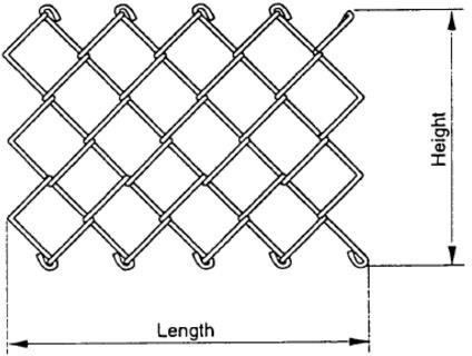
Chain link fencing may be supplied knuckled or with barbed ends, i.e. adjacent pairs of wire ends twisted together and cut at an angle . Any combination of these two presentations is used for the bottom and top of the fence.
3. Manufacturing
3.1 Base metal
The base metal of the chain link fencing shall be low carbon steel wire, which
shall be ordered as low tensile, i.e. less than 600 N/mm2, or high tensile greater than 600
N/mm2.Within any one supplied lot the tensile spread shall not exceed 150 N/mm2.
3.2 Fabrication
The fencing shall be fabricated from wires with the following types of coating:
a) zinc or zinc alloy coated to a minimum of pr EN 10244-1 and per EN 10244-2 class
A, subsequently organic coated to the appropriate part of prEN 10245-1, prEN 10245-2
or pr EN 10245-3, either:
i) extruded, not adherent;
ii) extruded, adherent;
iii) Sintered;
b) Zinc or zinc alloy coated to a minimum of pr EN 10244-1 and prEN 10244-2 class
C, subsequently organic coated to the appropriate part of prEN 10245-1, prEN 10245-2
or prEN 10245-3, either:
i) extruded, non adherent;
ii) extruded, adherent;
iii) sintered;
c) zinc or zinc alloy coated to a minimum of prEN 10244-1 and prEN 10244-2 class
D, subsequently organic coated to the appropriate part of prEN 10245-1, prEN 10245-2
or prEN 10245-3, either:
i) extruded, non adherent;
ii) extruded, adherent;
iii) sintered;
d) zinc alloy 95 Zn/5 A1 coated to a minimum of prEN 10244-1 and prEN 10244-2 class A;
e) zinc coated to a minimum of prEN 10244-1 and prEN 10244-2 class A;
f) zinc coated to a minimum of prEN 10244-1 and prEN 10244-2 class C;
g) bright wire subsequently organic coated to therequired part of prEN 10245-1, prEN 10245-2, prEN 10245-3
4. Requirements
4.1 Tensile strength
The wire shall be either:
- low tensile (less than or equal to 600 N/m2); or
- high tensile (greater than 600 N/mm2).Within any one delivered lot the tensile
strength spread shall not exceed 150 N/mm2
4.2 Wire diameters, chain link mesh sizes, heights and tolerances
Typical mesh size and tolerances, wire diameters and tolerance on heights are given in
Table 1. Typical heights are: 0,5 m; 0,8 m; 0,9 m; 1,0 m; 1,2 m; 1,4 m;1,5 m; 1,8 m; 2,0
m; 2,1 m; 2,4 m; 2,5 m; 3,0 m; 3,5 m;3,6 m; 4,0 m.For the wires which are coated with
zinc or zinc alloy the following tolerances on diameter shall apply
- Coated class A to prEN 10244-1 and prEN 10244-2:T1 of EN 10218-2 (Table 1)
- Coated class C to prEN 10244-1 and prEN 10244-2:T2 of EN 10218-2 (Table 1)
Table 1 -Chain link fencing mesh dimensions and tolerance, typical wire sizes and tolerance on height
| Dimensions in millimetres | |||
| Mesh | Nominal wire diameter | Tolerance on height | |
| Size | Tolerance | ||
| Zine alloy / zinc coated | |||
| 25 | ±2.0 | 2.0; 2.50 | ±30 |
| 40 | ±1.0 | 2.0; 2,50; 3.00; 3,55 | ±30 |
| 45 | ±4.0 | 2.0 | ±30 |
| 50 | ±4.5 | 2.0; 2.20; 2,50; 3,00; 3,55; 5,00 | ±40 |
| 60 | ±5.0 | 2.00; 2,20; 2.50; 3,00; 3,55; 5,00 | ±50 |
| 75 | ±5.0 | 2.50; 3,00 | ±60 |
| Organic material (extruded) coating over a zinc / zinc alloy coated or blight wire | |||
| 25 | ±2.0 | 1.90 / 2.65 | |
| 40 | ±4.0 | 1.90 / 2.65; 2,00 / 3,00; 2,25 / 3,15; 2.50 / 3.55 | ±30 |
| 45 | ±4.0 | 1,70 / 2,50; 1.80 / 2.70; 1,90 / 2,65; 2,25 / 3.15; 2.50 / 3,55 | ±30 |
| 50 | ±4.5 | 1.70 / 2,50; 1,80 / 2.70; 2,00 / 3.00; 2,25 / 3.15; 2,50 / 3,55; 3,00 / 4.00; 3,55 / 4.75; 4.75 / 6,40 | ±40 |
| 60 | ±5.0 | 1,70 / 2.50; 1.80 / 2.70; 2,00 / 3,00; 2,20 / 3,40; 2.50 / 3,80; 2.80 / 4.20; 3,10 / 4.60; 3,80 / 5,00 | ±50 |
| 75 | ±5.0 | 2.00 / 3.00; 2.25 / 3.15 | ±60 |
4.3 Coating
4.3.1 Zinc/zinc alloy coating
The zinc/zinc alloy coated wires shall be tested to the appropriate class of prEN 10244-2.
Where samples of zinc/zinc alloy coated wires are taken from a fabricated fence, the
specified minimum coating mass shall be reduced by 5 % and, where specified, the number
of dips shall be reduced by one min. The assessment of adherence (wrap quality) on 13
diameter of the zinc/zinc alloy coated wire prior to fabrication shall be in accordance
with quality of adherence 1 or 2 of prEN 10244-2. The assessment of adherence (wrap
quality) on 13 diameter of the wire in the fabricated fence shall comply with quality of
adherence 1, 2 or 3 of prEN 10244-2.
4.3.2 Organic coating material
When required, the organic coating shall comply with the relevant part of prEN 10245-1
and prEN 10245-2 or prEN 10245-3 given at the time of enquiry and order.
5. Sampling and testing
Pusheng shall be responsible for the control of product quality by the application of statistical
methods of sampling and analysis of results or, alternatively, by sampling and testing for the agreed
quality characteristics at a rate of one roll/reel in 50.
6. Inspection documentation
Unless otherwise agreed at the time of enquiry and order, non-specific testing and inspection
documentation shall be provided according to the requirements of EN 10021 and EN 10204.
7. Methods of test
7.1 Tensile testing
Tensile testing shall be in accordance with EN 10218-1.
7.2 Coating tests
7.2.1 Zinc/zinc alloy coating
The adherence and coating mass and, where requested, the coating uniformity of the wire used to
fabricate the chain link mesh shall be tested in accordance with prEN 10244-1 and prEN 10244-2.
7.2.2 Organic coating material
The wire coated with an organic material shall be tested in accordance with the appropriate part
of prEN 10245-1, prEN 10245-2 or prEN 10245-3
8. Steel Posts.
Steel posts and struts shall be produced from the following:
a) rolled steel angle (RSA)4) or angle re-rolled from railway lines5);
b) Rectangular or square hollow sections (RHS);
c) Circular hollow sections or round tubes;
d) I/H sections (rolled steel joists (RSJ), universal beams and universal columns);
Recommended dimensions for steel posts
| Height of fence | Posts | ||||||
| Length | Intermediate posts (section size) | Straining posts (section size) | |||||
| Rolled steel angle | Tube or circular hollow section | Rectangular hollow section | Rolled steel angle | Tube or circular hollow section | Rectangular hollow section | ||
| m | m | mm | mm | mm | mm | mm | mm |
| 0.90 | 1.50 | 40 x 40 x 5 | 33.7x2.6 | 40 x 40 x 2.5 | 50 x 50 x 6 | 48.3x3.0 | 50 x 50 x 3 |
| 1.20 | 1.80 | 40 x 40 x 5 | 33.7x2.6 | 40 x 40 x 2.5 | 50 x 50 x 6 | 48.3x3.0 | 50 x 50 x 3 |
| 1.40 | 2.00 | 40 x 40 x 5 | 42.4 x 2.6 | 40 x 40 x 2.5 | 60 x 60 x 6 | 60.3 x 3.0 | 50 x 50 x 3 |
| 1.80 | 2.50 | 50 x 50 x 5 | 42.4 x 2.6 | 40 x 40 x 2.5 | 60 x 60 x 6 | 60.3 x 3.0 | 50 x 50 x 3 |
| 1.80 with integral arms | 3.00 | 50 x 50 x 6 | 48.3 x 3.0 | 40 x 40 x 3.0 | 60 x 60 x6 | 60.3 x 3.0 | 50 x 50 x 3 |
| 2.15 | 2.80 | 50 x 50 x 6 | 48.3 x 3.0 | 40 x 40 x 3.0 | 60 x 60 x 6 | 60.3 x 3.0 | 50 x 50 x 3 |
| 2.15 with integral arms | 3.25 | 50 x 50 x 6 | 48.3 x 3.0 | 40 x 40 x 3.0 | 60 x 60 x6 | 60.3 x 3.0 | 50 x 50 x 3 |
9. Erection
i) Holes for straight posts will not be less than 450mm square and holes for struts not
less than 450mm long by 300mm wide. They will have vertical sides.
ii) The holes for staining posts will be filled up to a minimum of half their depth with
concrete. The concrete will be well rammed as filling proceeds. Before the
concrete has hardened the remainder of the hole will be filled with earth and well
rammed as the filling proceeds.
iii) Holes for intermediate posts will have vertical sides and be of sufficient size to
allow a 75mm surround of concrete. The concrete to be placed as for straining
posts.
iv) Straining posts will be provided at all ends and corners, at acute changes in level
and at intervals on the straight. Struts will be fitted to straightening posts in the
direction of each line of fence.
v) Line wires will be attached to intermediate posts by means of "hair pin" staples.
vi) Chain link mesh will be strained between each pair of straining posts by means of
stretcher bars and then attached to the line wires by wire ties 150mm apart on
the top wire and 450mm apart on the remaining wires.