We supply temporary security fence and permanent fence for construction sites.
Following is temporary fencing system ( chain link fabric type) for a construction project of our customers. Fence mesh types, posts, gates, barbed wire and concertina tapes can be custom made according to specific site requirements.
Temporary fence requirements as follows:
install, rental/upkeep and removal.
8' tall : 7' chain link with single strand barb wire at top
Rectangular plot area 400' x 750'
Double gate, 24' width at South end
Single personnel gate at South end
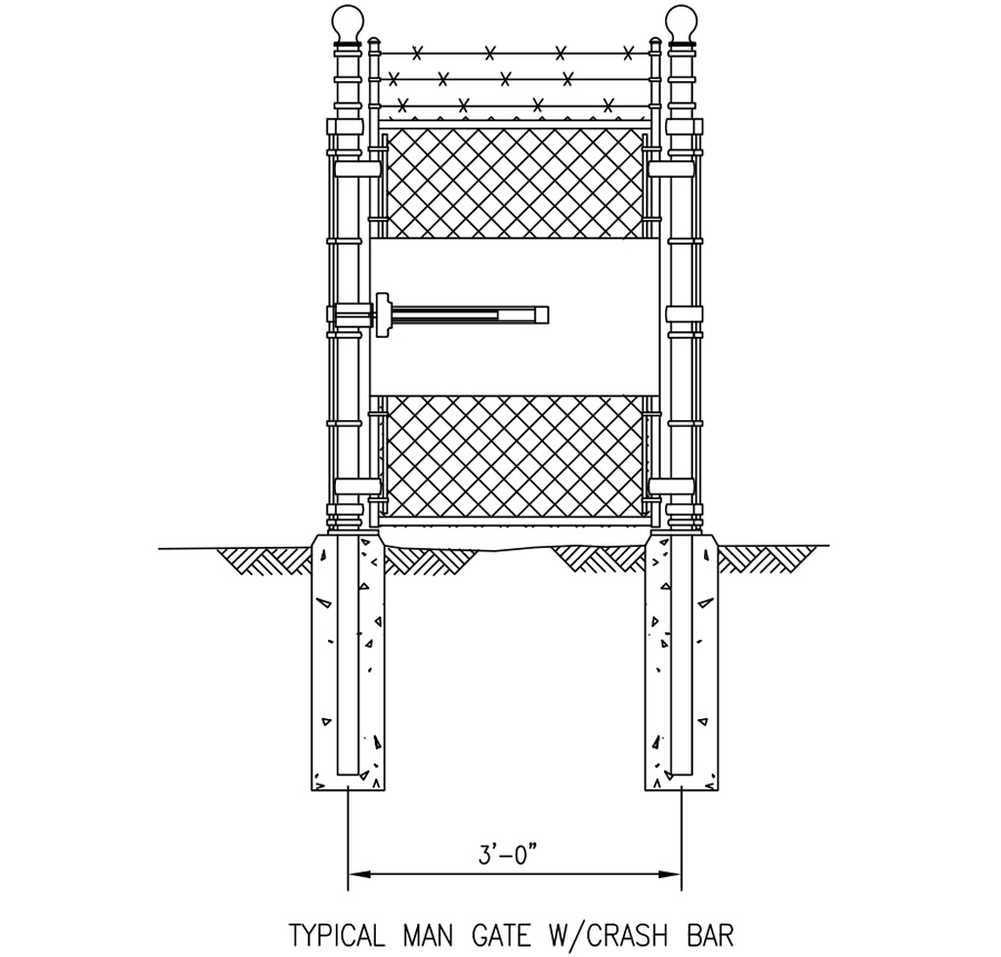
Single personnel gate with panic bar on West side.
Temporary Chain Link Fencing
Purpose and Requirements
Fences are installed to provide security, or a visible boundary between the facility and adjacent property. The fence is located as close as necessary to enclose the facility but no closer to the edge of the property than one foot inside the property line.
Fences as physical protection enclosures are used to guard against unauthorized access or accidental contact, provided with exposed energized electrical conductors and circuit parts.
Fence Style and Height
Chain Link Mesh Fence with Barbed Wire Lines
The security fencing, of chain link fabric, six feet high with top rail, bottom tension wire, and three strings of barbed wire on 45-degree extension arms projecting outward to provide an additional one foot height for a total height of seven feet.
Barbed-tape concertina wire may be substituted for or added in addition to the three strings of barbed wire on the extension arms. Local and governmental regulations may require fences around rural substations, and some facilities needed in construction sites, to be eight feet for the total fence height, including seven feet of fabric and a one-foot extension of barbed wire.
Fence Bottom Tolerances
Unless specified otherwise on the drawings or in the special instructions, the maximum gap between the fence fabric and closed gates is a maximum of 2 inches. If a gap of more than 2 inches is encountered between the bottom of the fence fabric and the finished grade, other measures can be employed. The use of additional barbed wire tension wires or bottom rails can be used if the 2-inch gap cannot be repaired by using additional fill.
Drainage Crossings
Fencing passing over ditches or swales is intended to provide protection to prevent unauthorized entry. Several methods can be used to achieve the objective of providing a gap of not more than 2 inches between the fence fabric and the earthen or concrete bottom of a ditch or swale.
Line Posts, End Posts, Corner Posts, Pull and Gate Posts
(1)All posts shall be galvanized steel pipe as per Table 3-1 below, conforming to ASTM F1043 or ASTM A53/A53M. Zinc coating shall be 2 ounces per square foot of rod surface as determined by ASTM A90.
(2)Changes in line where the vertical angle of deflection exceeds 20 degrees shall be considered as corners, and corner posts and bracing shall be installed.
(3)Posts shall be installed at 10-foot centers maximum and equal spacing; plumb both ways. Posts shall be placed vertically except as may be specifically designated otherwise.
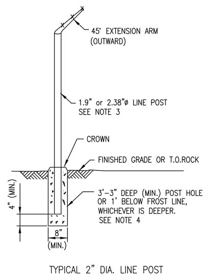
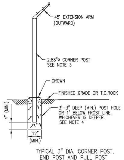
Table 1 Post Specifications
| Type of Post | Single Gate Opening (ft) | Double Gate Opening (ft) | NPS (inches) | Gate Posts Outside Diameter (inches) and Pipe Schedule | Weigh lb/ft |
| Swing Gate | Up to 6 (ft) | Up to 12 (ft) | 2-1/2 | 2.88 inch schedule 40 Pipe. | 5.79 |
| Swing Gate | 6 to 13 (ft) | 12 to 26 (ft) | 3-1/2 | 4.00 inch schedule 40 pipe. | 9.11 |
| Swing Gate | 13 to 18 (ft) | 26 to 36 (ft) | 6 | 6.63 inch schedule 40 pipe. | 18.97 |
| Swing Gate | 18 to 26 (ft) | 8 | 8.63 inch schedule 40 pipe. | 28.55 | |
| Sliding Gate | Up to 26 (ft) | 3-1/2 | 4.00 inch schedule 40 pipe. | 9.11 | |
| Sliding Gate | 26 to 36 (ft) | 6 | 6.63 inch schedule 40 pipe. | 18.97 | |
| Sliding Gate | 36 to 62 (ft) | 8 | 8.63 inch schedule 40 pipe. | 28.55 | |
| End, Corner, Angle, and Pull | 21/2 | 2.88 inch schedule 40 pipe. | 5.79 | ||
| Line | 11/2 | 1.90 inch schedule 40 pipe. | 2.72 | ||
| Line (Alt.) | 2 | 2.38 inch schedule 40 pipe. | 3.65 |
Foundations
(1)All posts shall be set in holes and backfilled with concrete. The concrete shall have a minimum compressive strength of 2500 psi at 28 days with a maximum size of aggregate of one inch. (Strength testing of concrete is not required.) The concrete shall be well worked (rodded) in the hole. The top of the footing shall be crowned to shed water and shall be set 1/2 inch below the bottom of the fence fabric and sloped to shed water.
(2)Table 2 contains the minimum requirements for foundation size and post embedment for installing fence posts under normal conditions. The foundation depth shall not be less than the local frost line. If the construction drawing specifies a greater depth, that depth shall be the minimum depth.
(3) Where solid rock is encountered, a hole two inches larger than the post O.D. shall be drilled and grout or sand shall be placed around post.
Table 2: Post Foundation Specifications
| Foundation Diameter | Foundation Depth | Post Embedment | |
| 1.90" Line Post | 12" | 3'-3" | 3'-0" |
| 2.38" Line Post (Alt.) | 12" | 3'-3" | 3'-0" |
| 2.88" End, Corner, Angle and Braced Post | 12" | 3'-3" | 3'-0" |
| 4.00" Gate Post | 12" | 3'-3" | 3'-0" |
| 6.63" Gate Post | 18" | 3'-9" | 3'-6" |
| 8.63" Gate Post | 18" | 4'-3" | 4'-0" |
Grading
In non-graded areas, follow the existing ground line. Minor irregularities should be removed or filled by grading up to two feet on each side of the fence, but within the property line. Consideration should also be given to maintain a 6-foot clear zone inside and outside of the fence. If the fence is on the property line, (one foot inside property line) then provisions should be made to keep vegetation clear between the outside of the fence and the property line. Grading should be planned with a goal of maintaining no more than a 2-inch gap between the bottom of the fence fabric and finished grade line.
Gate Locations
(1)An assessment of each newly constructed or newly augmented facility's perimeter fencing should be performed for the purpose of determining if emergency exit gates are needed, and if so, to identify the location(s). A representative from the local operating area and the local Safety Department should be consulted during the assessment.
(a)Emergency exit gates should be provided when perimeter fencing prevents workers from reaching a safe place.
i.If the perimeter fencing is far enough away from the hazardous area, a safe place may be considered to be inside the fence and an exit not necessary.
ii.For small, normally unstaffed locations, such as valve sites, the access gate can be left open while work is being performed. This will provide for the emergency exit.
(b)When emergency exit gates are needed, a minimum of two will be provided, in as much as is possible, directly opposing sides of the site. This will provide an exit if wind conditions or the location of the emergency prevents access to one exit, the other exit will be available.
(c)For larger sites, equipment placement, congestion, and distance should be taken into consideration when identifying the location(s) for emergency exit gates. Consider locating an emergency exit gate every 200 feet as a baseline. This can be reduced or expanded depending on the proximity of the hazard and difficulty in accessing a safe place.
(d)Consideration should be made for the location in which the perimeter fencing emergency gate discharges. If the area is not public, or discharges into a neighboring facility, permission to do so might need to be obtained.
(e)Each fence around a compressor station must have at least two gates located so as to provide a convenient opportunity for escape to a place of safety, or have other facilities affording a similarly convenient exit from the area. Each gate located within 200 feet (61 meters) of any compressor plant building must open outward and, when occupied, must be openable from the inside without a key.
(2)Emergency Exit Gate Construction (If required from the assessment).
(a)Emergency exit gates shall be provided with panic hardware that allows the worker to exit without a key, but provides facility security from the exterior.
(b)Emergency exit gates shall have highly visible signs prominently displayed on the interior of the fence-line or gate identifying them as an "Emergency Exit."
Gate Frames
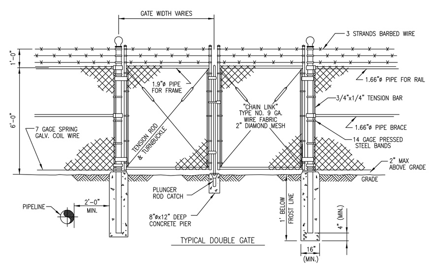
(1)Gate frames shall be constructed of tubular steel members that shall be welded at the joints. Additional horizontal, vertical, and/or diagonal struts may be required to provide for a rigid gate panel allowing for no visible sag or twist. Gate frames shall be made to have approximately three inches of clearance above the road. Fabric for the gate panels shall be the same as for the fence.
(2)Gate frame and bracing members shall not be less than the structural equivalent of 1-1/2 NPS (1.9 inch O.D.) standard galvanized pipe, 2.72 pounds per foot, conforming to ASTM A53 / A53M Grade B. Steel tension rods and turnbuckles may also be used. Gate frame shall have provisions for three lines of barbed wire above the fabric. All gate frame material shall be hot-dip galvanized.
Gate Style and Hardware
(1)Gates: either swing or sliding style.
Gates shall be the same height as the fence, complete with latches, stops, keepers, and three strands of barbed wire extending one foot above the top horizontal member (swing gate extensions may need to be turned in the opposite direction of the fence section to allow for opening the gate).
Gates provided with the same fabric and barbed wire used for the fence, and shall be furnished with additional horizontal and/or vertical members to ensure proper operation and for attachment of fabric, hardware, and accessories.
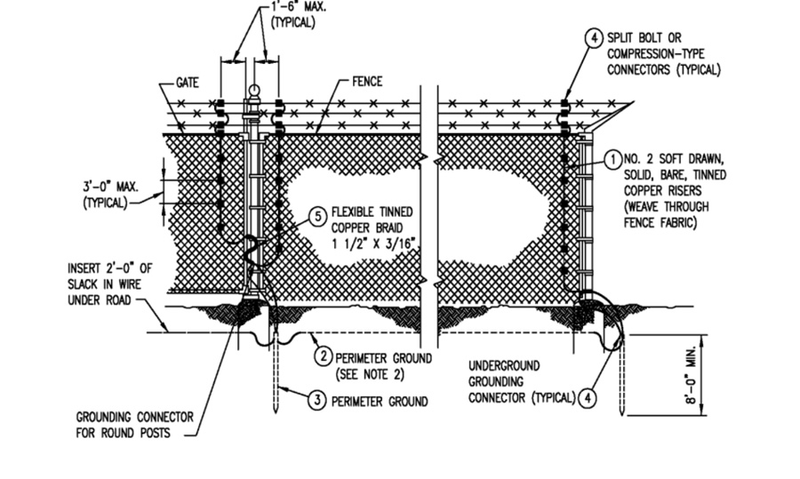
Typical Chain Link Fence Grounding
Facility perimeter fencing is not required to be grounded in general. However, the location and proximity to electrical power lines may require additional grounding. If an electric power line is running parallel and in close proximity to the facility perimeter fence, the fence should be grounded at intervals not more than 200 feet. This can be accomplished by installing a ground rod, or attaching to the ground loop for the facility. If an electric power line crosses a facility perimeter fence, the fence should be grounded within 100 feet on each side of the crossing. Personnel exit gates equipped with a panic bar should be grounded. The gate can be grounded using a single ground rod or ground loop connection connected to a braided flexible copper wire and the fence.
Inspections
The materials and fabrication shall be subject to inspection and approval in addition to those required by code. The waiver or approval of inspection shall not relieve the Vendor of responsibility to meet the requirements of the applicable codes and this standard.
Gates shall be hung by at least two galvanized steel or malleable iron hinges, three inches or more in width, which allow the gate to swing 180 degrees. Each hinge shall be strong enough to carry the vertical load.
Single swing gates shall have a fork latch. Double gate latches shall have a plunger-bar arranged to engage the center stop. Provide padlocking device for all latches. Provide keepers for all vehicle gates that automatically engage the gate leaf and holds it in the open position until manually released.
Provide gate stops for all double swing gates consisting of mushroom type or flush plate with anchors. Set in concrete to fully engage the center drop rod or plunger bar.
Extension Arms and Post Tops
(1)The extension arms shall extend upward and outward from the fence at an angle of 45 degrees. There shall be provisions for three equally spaced lines of barbed wire on the extended arms. The uppermost wire shall be approximately one foot vertically above the fabric.
(2)The extension arm shall be made of pressed steel or malleable iron and should be designed for a 250-lb minimum pull-down load being applied at arm's tip.
(3)The extension arm shall be galvanized in accordance with ASTM A153, Class Bl.
(4)All posts and gates shall be equipped with either post tops or extension arms for barbed wire. All extension arms and post tops shall be designed to exclude moisture from post interior.
Top Rails
Top rails shall be either 1.66 inch O.D. (11/4 inch NPS) Schedule 40 pipe, weighing 2.27 pounds per linear foot or 1.90 inch O.D. (11/2 inch NPS) Schedule 40 pipe, weighing 2.72 pounds per linear foot conforming to ASTM F1043 - 08, complete with couplings approximately every 20 feet. Couplings shall be outside sleeve type and minimum of 6 inches long. One coupling in every five shall have a heavy spring to take up expansion and contraction of top rail. Top rail shall pass through the base of the line post tops and form a continuous brace from end to end of each stretch of fence. Top rail shall be securely fastened to terminal posts by pressed steel connections.
Braces
(1)All end, corner, angle, and gate posts shall be braced. Line posts shall be braced in both directions at intervals not to exceed 800 feet.
(2)Braces shall be 1.66 inch O.D. (11/4 inch NPS) Schedule 40 pipe, weighing 2.27 pounds per linear foot or 1.90 inch O.D. (11/2 inch NPS) Schedule 40 pipe, weighing 2.72 pounds per linear foot conforming to ASTM F1043-08. Braces shall be installed midway between the top of the fence and grade and extending horizontally from terminal and gate posts to the first adjacent line post. Braces shall be securely fastened to posts by heavy pressed connectors, and trussed from line posts to terminal post with 3/8 inch diameter adjustable truss rod. Corner and angle posts shall be braced each way. Provide one brace and two truss rods for each end or gate post and one brace and one truss rod in each direction at each corner and pull post.
Tension Wire
Seven gauge spring coil tension wire shall be located at the bottom of the fence fabric. The tension wire shall be in accordance with ASTM A121 and Class 2 galvanizing.
Fittings
All fittings shall be malleable cast iron and pressed steel with hot-dip galvanized coating and conform to ASTM F626. Miscellaneous material shall be galvanized as specified in ASTM Designation A123 and A153.
Chain Link Fence Fabric
(1)Chain link fence fabric in accordance with ASTM A392 with Class 2 galvanizing.
(2)Chain link fabric woven of No. 9 gauge woven steel wire, six feet high commercial quality steel wire hot-dipped galvanized after weaving to Class I weight of coating, not less than 1.20 ounces per square foot of actual wire surface covered. Excessive roughness, blisters, sal ammoniac spots, bruises, or flaking may provide a basis for rejection.
The fabric has a uniform diamond mesh approximately two inches between the parallel sides. Top and bottom selvages shall have a twisted and barbed finish.
(3)Gate fabric is attached to gate frames in a manner similar to that used to attach the fence fabric.
Notes:
1. Perimeter ground wire should be continuous cable connected to fence posts, to all gate posts, and to all corners.
2. Wire to be looped through ground rod clamps and fence clamps to keep spuces to a minimum.
3.Minimum fence height is seven (7) feet. Normally consist of six (6) feet of fabric and a one (1) foot extension of barbed wire. Recommends eight (8) feet for the fence height; seven feet of fabric and a one foot extension of barbed wire. Where local ordinances prohibit the use of barbed wire, the fence fabric must be increased to seven (7) feet, barbed wire overhang away from the substation yard.
Fabric Connections
(1)The wire fabric is securely fastened to all terminal posts by 1/4 inch x ¾ inch tension bars with 14 gauge minimum pressed steel bands on about 14 inch centers, to all line posts on about 24 inch centers.
(2)No. 9 gauge galvanized wire ties in accordance with ASTM A-02 and ASTM A641 is used to fasten the fabric to line posts at a spacing not to exceed 15 inches, and to the top rail at a spacing not to exceed 24 inches. For tension wires and braces, furnish tie wire approximately 24 inch apart.
Barbed Wire
Three strands of barbed wire shall be installed running the entire length of fence above fabric at approximately 45 degrees (barbed wire on swing gates may need to be turned inward or vertical with interconnection to the outward barbed wire at hinge end of the gate to allow opening the gate). Each strand shall consist of two 121/2 gauge wires with 14 gauge barbs in a four point pattern on five inch centers. All wire shall be galvanized in accordance with ASTM A121 Class 3. The three strands shall be supported at the line and corner posts by an extension arm at 45 degrees, carrying three strands and capable of supporting a minimum of 250 pounds vertical dead load from the tip of the arm. The barbed wire shall be tied off at terminal posts that shall extend one foot higher than the line posts.
Barbed Tape/Concertina
Barbed-tape concertina is a commercially manufactured wire coil constructed of high strength-steel barbed wire that is clipped together at intervals to form a single coil or double coil. Barbed tape concertina may be added to the top and, in some cases, to the bottom to increase the level of protection. Barbed tape concertina must be secured at a minimum interval of 18 inches (457 mm) along the fence fabric to the top barbed wire strand and a maximum gap of 2 inches (51 mm) should be maintained between the bottom barbed wire and the top of the chain-link fabric. Barbed tape concertina wire is not to be used on fences with fence fabric less than 7 feet.
Fence Erection
(1)Perform the necessary clearing, excavation, and filling to provide clear "line of fence" runs.
(2)Install corner or pull posts or vertical angle point of 20 degrees at no more than 800 foot intervals.
(3)After posts are installed and concrete has set firmly, place top rail and bottom tension wire, and securely anchor at ends and to line posts before hanging fabric.
(4)All fabric shall have tension wire approximately five inches above grade on bottom of fence.
(5)Secure ends of fabric with tension bars threaded through loops in the fabric and attached to posts by specially designed fasteners or bands with nuts and bolts. Bands shall comply with ASTM A153.
(6)The fabric shall be placed on the outside of the posts, stretched taut, and secured to the posts, top rail, and tension wire. The fence shall be stretched to produce enough tension to cause wire to feel springy to the touch. Wire shall not be stretched around a corner, which changes the direction of the fence line more than 45 degrees; instead, the fence shall be cut and wired to the post. Splices shall be made at the brace or pull posts.
(7)The fabric shall be secured to the line posts with wire ties or metal bands at maximum intervals 14 inches. The top and bottom edges shall be secured, respectively, to the top rail and tension wire with tie wires not exceeding intervals of 24 inches. The fabric shall be secured to terminal posts by means of the stretcher bar that is passed through the end loops of the fabric and is secured to the terminal posts by metal bands spaced at a maximum interval of 14 inches. The fence shall be staked down where required.
Gate Erection
(1)Gate installation shall include gate frames, tension bars, fabric, latches, stops, locking devices, hinges, gate posts with braces, tie rod, take-ups, caps, and all fittings and details for gates and gate posts, all as specified, shown on the drawings and as required to make up a complete installation. Gates shall be aligned with posts vertical. Clamps used for attaching hardware shall be made up tight. The bottom of each gate shall clear the ground by three inches at all points in its swing. The Seller shall modify the existing grade to meet this requirement if necessary, as directed by the Purchaser.
(2)Stops shall be provided for all gates to prevent damage to the gate or fence by over swing, and to arrest the swing of a closed gate at the centerline of the fence. Keepers shall be provided to automatically catch the gate when swung open, and to hold it in this position.
Field Touch-Up of Galvanizing
Repairs of galvanized coating shall be made with ZRC Cold Galvanizing Compound. Damaged surface shall be cleaned of all rust and prepared in accordance with clients's instructions prior to application of compound.
Chain link fence standard detail Notes:
1,all sites to have two (2) gates, one for vehicle entrance and one for walk through each gate shall be located at opposite sides of enclosure. gate with crash bar shall swing open outward.
2, ence shall be electronically grounded.
3. fence posts foundations to be a minimum 2' from all pipelines.
4. local building codes and permits prevail.
5. all fence and gate material to be hot dip galvanized.
6. end of imbedded post to be 3" above bottom of concrete.